
Piping Design Checklist for Accurate Engineering Drawings
Piping Design Checklist for Accurate Engineering Drawings
Source: KnowPipingField.com
II JAY SHRI KRISHNA II
In industrial plant design, piping layouts are vital for the smooth operation and safety of process systems. A minor oversight can lead to costly delays, rework or even critical failures. This blog post titled “Piping Design Checklist for Accurate Engineering Drawings” serves as a complete guide to ensure your piping layouts meet industry standards, interdepartmental coordination and safety compliance.
Piping Design Checklist:
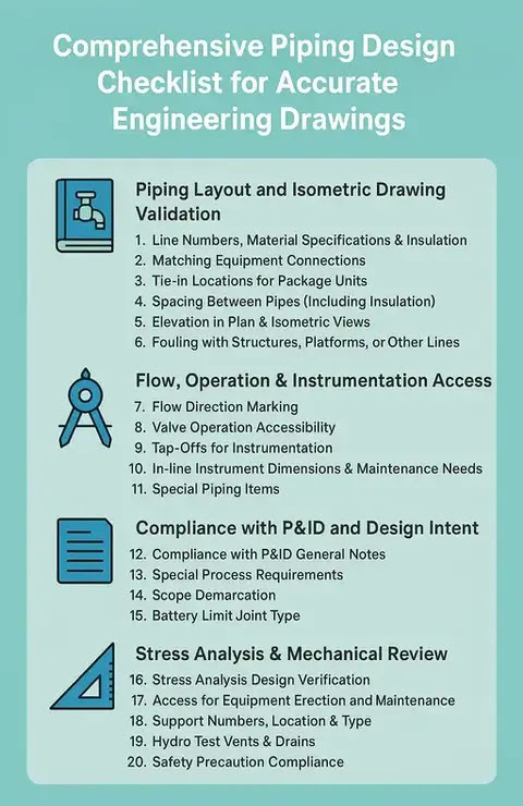 |
Piping Design Checklist for Accurate Engineering Drawings |
Whether you’re a piping designer, project engineer or QA/QC personnel, this detailed checklist will help you validate every element of your design — from line numbers to valve accessibility and from fouling checks to support locations.
📘 Piping Layout and Isometric Drawing Validation
- Line Numbers, Material Specifications & Insulation
- Check that each line number is well-defined and the material specification & insulation class match the P&ID diagrams.
- Matching Equipment Connections
- Verify that piping connections at equipment nozzles, pipe headers and continuation drawings (both above ground and underground) are correctly aligned.
- Tie-in Locations for Package Units
- Tie-in points for packaged units must be clearly marked with proper connection types (e.g., flanged, threaded, welded) and accessible locations.
- Spacing Between Pipes (Including Insulation)
- Maintain adequate clear spacing between adjacent lines, especially when insulation is applied, to prevent heat transfer, fouling or damage.
- Elevation in Plan & Isometric Views
- Double-check centerline elevations in both plan and isometric views for consistency with design intent and clash-free routing.
- Fouling with Structures, Platforms or Other Lines
- Ensure there are no interferences with nearby lines, support structures, cable trays or operator platforms.
🧭 Flow, Operation & Instrumentation Access
- Flow Direction Marking
- Mark the flow direction of each line clearly using standard arrows and symbols.
- Valve Operation Accessibility
- Confirm that manual and actuated valves are placed within ergonomic reach and accessible for operation without obstructions.
- Tap-Offs for Instrumentation
- Tap-off points for pressure, flow, temperature and level instruments must be appropriately located for both process integrity and maintenance.
- In-line Instrument Dimensions & Maintenance Needs
- Leave adequate space for removal of instruments like flowmeters, control valves or strainers, especially those installed in vertical lines.
- Special Piping Items
- Items like strainers, rupture discs or expansion joints must be clearly marked and noted in both layout and isometric drawings.
📑 Compliance with P&ID and Design Intent
- Compliance with P&ID General Notes
- Review all general notes, legends and abbreviations from the referenced P&ID diagram to ensure design intent is preserved.
- Special Process Requirements
- Address any unique process constraints, such as high-purity lines, jacketed piping, or heat tracing that may not be standard.
- Scope Demarcation
- Define the interface boundaries between piping and other stakeholders like instrumentation, package vendors or clients.
- Battery Limit Joint Type
- Identify the joint type at battery limits (e.g., welded, flanged, mechanical coupling) for ease of tie-ins and future modifications.
📐 Stress Analysis & Mechanical Review
- Stress Analysis Design Verification
- Ensure the piping design has been validated through pipe stress analysis software like CAESAR II or Start-Prof and meets code compliance.
- Access for Equipment Erection and Maintenance
- Leave necessary clearances around pumps, vessels and exchangers for maintenance activities, including crane or forklift access.
- Support Numbers, Location & Type
- Identify and label each pipe support (spring, anchor, guide, hanger, etc.) with its location and type clearly in layout drawings.
- Hydro Test Vents & Drains
- All low-point drains and high-point vents must be marked for hydrotesting and fluid removal.
- Safety Precaution Compliance
- Ensure design complies with plant safety regulations, such as escape routes, explosion zones, and non-obstruction of safety systems.
👁️ Aesthetic, Utility & Safety Considerations
- Aesthetic Layout
- Maintain a neat and logical pipe routing pattern to reduce complexity and improve visual clarity.
- Hose Station & Eye Washer Locations
- Show proper locations for hose stations and safety showers/eye washers near chemical handling or hazardous areas.
- UG Piping Coordination
- Check that all underground piping matches the UG piping layout drawings with correct depth, protection, and routing.
- Instrument Tag Numbers
- Assign a unique instrument tag number from the project's instrumentation index to each tap-off.
- Equipment Numbering & Elevation
- All equipment (vessels, exchangers, tanks) must be labeled with equipment tag numbers and centerline elevation indicated.
🔧 Piping Supports, Traps & Tracing Systems
- Proper Pipe Support Adequacy
- Check that supports are designed to carry thermal expansion, vibration and dead load without sagging or overloading.
- Safety relief discharge piping must be supported with guides and anchors, ensuring no blow-back or vibration issues.
- Steam Trap at Low Points
- Install condensate steam traps at all low points to remove accumulated condensate effectively.
- Instrument Air & Steam Trace Manifolds
- Check for the presence and accessibility of instrument air headers & steam trace manifolds with proper tags & drain valves.
🤝 Interdepartmental Coordination Checklist
- Process Department Comments
- Confirm all design changes requested by the Process Department have been incorporated, especially for fluid service and temperature class.
- Instrumentation Department Comments
- Address feedback regarding tubing routes, junction box access or signal cable interferences.
- Client and Statutory Body Comments
- Ensure all client feedback and regulatory compliance changes are implemented, especially for environmental or fire safety zones.
Frequently Asked Questions (FAQs)
1. What is a piping design checklist?
A piping design checklist is a structured document used by engineers to verify that piping layouts, isometric drawings, material specifications, supports, safety requirements, and multidisciplinary coordination have been completed before issuing drawings for construction.
2. Why is a piping design checklist important?
A piping design checklist helps identify design errors early, reduces rework during construction, improves safety, ensures compliance with engineering standards, and enhances overall project quality.
3. What important factors should be checked during the review of a piping layout?
A piping layout drawing should be checked for line numbers, equipment connections, pipe routing, elevations, clearances, support locations, valve accessibility, insulation requirements, hydrotest vents and drains, and safety clearances.
4. Why should piping drawings be coordinated with other engineering disciplines?
Coordination with civil, structural, process, instrumentation, electrical, and mechanical teams helps prevent clashes, ensures constructability, and supports safe and efficient plant operation.
5. What is the purpose of hydrotest vents and drains in piping systems?
Hydrotest vents remove trapped air during testing, while drains allow complete removal of test water after hydrostatic testing, helping ensure safe and effective pressure testing.
6. Why are pipe supports important in piping design?
Pipe supports carry the weight of piping, control thermal movement, reduce vibration, protect connected equipment, and maintain long-term system reliability.
7. What common mistakes can be avoided by using a piping design checklist?
A checklist helps prevent incorrect material specifications, missing supports, insufficient maintenance access, piping clashes, inconsistent elevations, incomplete line numbering, and overlooked safety requirements.
8. Who should use a piping design checklist?
Piping designers, piping engineers, project engineers, QA/QC inspectors, design reviewers, EPC contractors, and construction engineers can all benefit from using a piping design checklist throughout a project.
✅ Conclusion: Don't Miss a Step in Piping Design
A well-reviewed piping design is more than just clean drawings—it's the foundation for safe, efficient, and cost-effective plant operations. Following a comprehensive checklist helps engineers detect issues early, avoid installation delays, and meet compliance standards with confidence.
As project timelines tighten and inter-discipline collaboration becomes more essential, this checklist serves as your go-to guide for piping accuracy and quality assurance. From material specs to valve access, and from stress validation to hydrotest readiness—every item counts.
Use this guide across all stages of your piping project to minimize errors, improve plant uptime, and maintain professional excellence. Bookmark it. Print it. Share it with your team. Because good design starts with good checking.
✅ Your downloadable checklist PDF is ready!
📥Click below to download the full checklist PDF for Piping Design Engineering Drawings:
👉 Download Checklist PDF
📝 Prepared By: Know Piping Engineering
📝 Prepared By: Know Piping Engineering
🚀 For more insights, check out these related posts:
Checklist for Piping & Instrumentation Engineering Drawings Review
Checklist for Piping Engineers: Plot Plan and Equipment Layout
Guidelines for Developing an Equipment Layout Drawing
Piping GA Drawing: A Comprehensive Guide Series - Part 1: Fundamentals
Piping Interview Preparation: Site Selection, Plot Plans & GA Drawings
Checklist for Civil & Structural in Piping Layouts
How to Conduct a Successful Piping Walkdown Inspection
Diagnosing Vibration Issues in Pump-to-Pipe Connections (With Case Study)
How to Design & Select Bellows for Long-Life Piping Flexibility
Pipe Supports and Restraints: Types, Functions & Design Best Practices
Best Practices for Header & Nozzle Loads in Piping Systems
Allowable Nozzle Loads – API 610 & WRC 107/297 Guide
Fluid Transient Analysis | Preventing Water Hammer in Piping
Please like, message and share if you feel all my blogs are beneficial, useful or helpful for you and for other also.
Thank you so much for following my blog…!! 🙏
See you all in the next coming blogs till then keep exploring piping field……!!
Have a great day today.... Keep smiling 😀 and God Bless You all…!!
To be continued……


Post a Comment